Difference between revisions of "CellularMemory:Biological Designs"
Wideloache (talk | contribs) (→Mutual Repression) |
Wideloache (talk | contribs) (→Autoregulatory Positive Feedback) |
||
| (11 intermediate revisions by the same user not shown) | |||
| Line 1: | Line 1: | ||
{{DeLoache Top}} | {{DeLoache Top}} | ||
| − | + | __NOTOC__ | |
| − | =<center>Biological | + | =<center>Biological Designs</center>= |
==Overview== | ==Overview== | ||
| − | Thus far in the construction of various synthetic cellular memory devices, two main biological | + | Thus far in the construction of various synthetic cellular memory devices, two main biological designs have been used by researchers: [[CellularMemory:Biological Models#Mutual Repression | mutual repression]] and [[CellularMemory:Biological Models#Autoregulatory Positive Feedback | autoregulatory positive feedback]]. Both of these designs produce two stable levels at which a reporter protein can exist in a given cell. Based on a given input, both models balance reporter protein concentrations to one of these two stable states (typically "on" or "off") through a specific configuration of genes and promoters. Both the mutual repression model and the autoregulatory positive feedback model are found in natural systems, but each equips a synthetic device with different capabilities. The mutual repression design works by turning off expression of one or more constitutively expressed genes based on an input, while autoregulatory positive feedback turns on one or more constitutively repressed genes based on an input. |
==Mutual Repression== | ==Mutual Repression== | ||
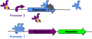
[[Image:Offstate.png|thumb|300px|right|'''Figure 1:''' Depiction of a mutual repression system in the "off" state.]] | [[Image:Offstate.png|thumb|300px|right|'''Figure 1:''' Depiction of a mutual repression system in the "off" state.]] | ||
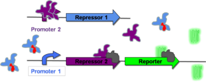
[[Image:Rep2 Bound.png|thumb|300px|right|'''Figure 2:''' Depiction of a mutual repression system in the "on" state.]] | [[Image:Rep2 Bound.png|thumb|300px|right|'''Figure 2:''' Depiction of a mutual repression system in the "on" state.]] | ||
| − | The mutual repression | + | The mutual repression design can fuction as a genetic toggle switch, capable moving between two stable states. This system was first implemented in ''E. coli'' in 2000 and will be the focus of the first paper discussed ([[CellularMemory:References |Gardner, 2000]]). Mutual repression relies on the use of two constitutive promotors that regulate the transcription of repressor genes. As can be seen on the right, both promoters are placed upstream of the repressor-pair for the opposite promoter. When a given promoter is active, it shuts down transcription of its own repressor-pair by transcribing the repressor gene for the opposite promoter. This allows the cell to remain in one of two stable states. |
| − | Figure 1 shows a system in which Promoter 2 is active and Promoter 1 is repressed. This state arises because of the presence of an inactivator molecule of Repressor 2 (shown in orange). The inactivator molecule binds to any Repressor 2 in the cell, allowing for transcription of Repressor 1. (The gray molecule represents RNA Polymerase.) Repressor 1 then binds to Promoter 1 and represses any further transcription of Repressor 2 or the downstream reporter gene. At this point, the cell is in a stable state, where Repressor 2 is expressed and Repressor 1 and the reporter protein are not. This will be | + | [http://gcat.davidson.edu/GcatWiki/index.php/Image:Offstate.png Figure 1] shows a system in which Promoter 2 is active and Promoter 1 is repressed. This state arises because of the presence of an inactivator molecule of Repressor 2 (shown in orange). The inactivator molecule binds to any Repressor 2 in the cell, allowing for transcription of Repressor 1. (The gray molecule represents RNA Polymerase.) Repressor 1 then binds to Promoter 1 and represses any further transcription of Repressor 2 or the downstream reporter gene. At this point, the cell is in a stable state, where Repressor 2 is expressed and Repressor 1 and the reporter protein are not. This will be referred to as the "off" state. |
| − | The system can, however, be switched to the "on" state if an inactivator of Repressor 1 is introduced into the system | + | The system can, however, be switched to the "on" state if an inactivator of Repressor 1 is introduced into the system. This state is represented in [http://gcat.davidson.edu/GcatWiki/index.php/Image:Rep2_Bound.png Figure 2]. Here, the inactivator of Repressor 1 (shown in red) prevents repression of Promoter 1. This allows for transcription of both Repressor 2 and the reporter gene. Repressor 2 represses transcription of Repressor 1, and the reporter protein changes the phenotype of the cell to the "on" state (in this case, green fluorescence). |
| Line 23: | Line 23: | ||
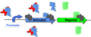
[[Image:Posfeedon.png|thumb|300px|right|'''Figure 4:''' Depiction of a autoregulatory positive feedback system in the "on" state.]] | [[Image:Posfeedon.png|thumb|300px|right|'''Figure 4:''' Depiction of a autoregulatory positive feedback system in the "on" state.]] | ||
| − | + | The autoregulatory positive feedback design refers to a gene network that contains a constitutively repressed promoter upstream of its activator gene. This genetic construct creates a positive feedback loop, where initial activation of the promoter causes transcription of an activator gene and thus further increases promoter strength. This positive feedback eventually converges to a steady state of gene expression ([[CellularMemory:Mathematical Models |see mathematical modeling]]). Autoregulatory positive feedback is the biological design used in the final two papers that will be discussed ([[CellularMemory:References |Kramer, 2005]] and [[CellularMemory:References |Ajo-Franklin, 2007]]). | |
| + | |||
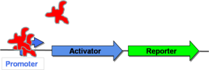
| + | In [http://gcat.davidson.edu/GcatWiki/index.php/Image:Posfeedoff.png Figure 3] to the right, the promoter is initially repressed by a protein that is native to the cell. This means that neither the activator nor the reporter gene will be transcribed. This cell is, therefore, in the "off" state. | ||
| + | |||
| + | In order to switch to the "on" state ([http://gcat.davidson.edu/GcatWiki/index.php/Image:Posfeedon.png Figure 4]), some stimulus must first allow for some low level of promoter activation. Once the promoter is activated, it will transcribe both its activator gene and the reporter gene. The activator protein in Figure 4 functions by binding to the native repressor protein and inactivating it. As more activator is produced, higher levels of gene expression will be observed. Eventually, the cell will arrive at a maximum level of gene expression at which point it is considered to be in the "on" state (in this case, green fluorescence). | ||
[[Image:linebreak.png]] | [[Image:linebreak.png]] | ||
Latest revision as of 18:44, 6 December 2007
Main Page | Biological Designs | Mathematical Models | Toggle Switch | Hysteresis | Permanent Memory | Conclusions | References
|


